Industrial Automation – Physical Measurement Blog
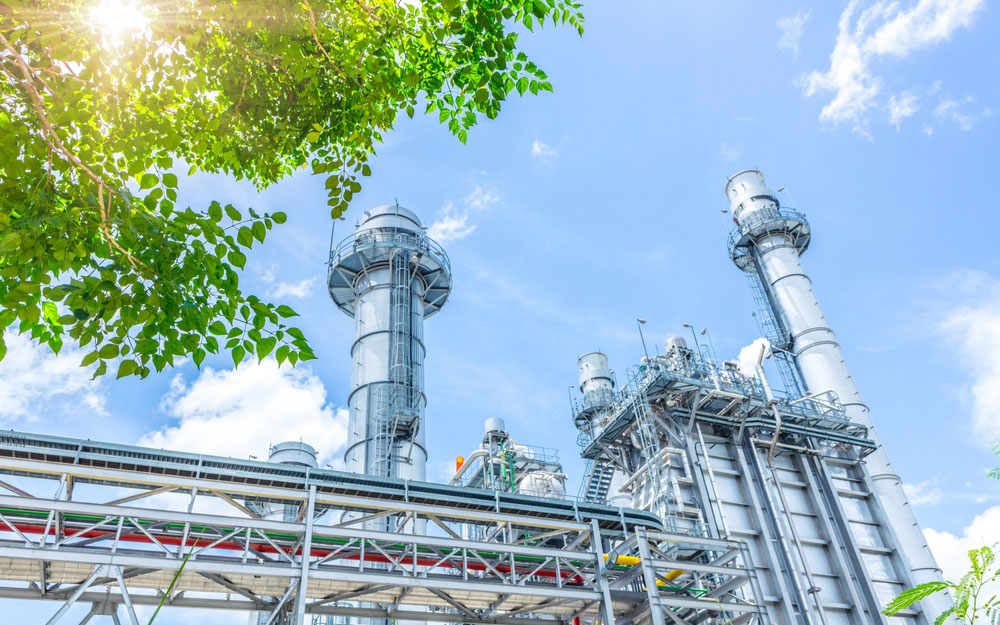
Carbon Footprint Solutions from Fuji Electric
Fuji Electric
There has been an increased interest in understanding how companies operations may be contributing to carbon dioxide emissions...
read more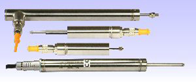
RDP's DCW Submersible LVDTs
RDP Electrosense
RDP Electrosense specializes in precise Linear Variable Differential Transformer (LVDT) type instrumentation...
read more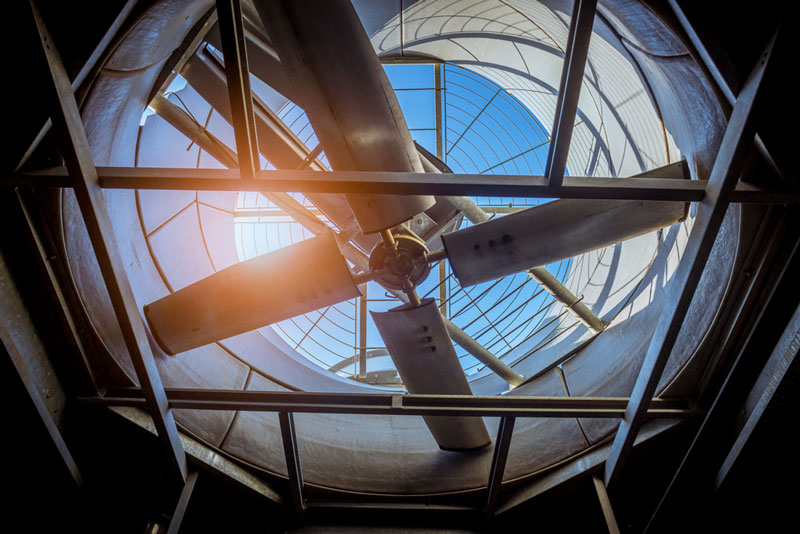
Wilcoxon's Low Frequency Sensors
Wilcoxon Sensing Technologies
Using low frequency (LF) sensors to monitor vibration on slow turning...
read more
Contact Us